


APS Arizona Rover - Do-It-Yourself Guide
 Just
like the Mars Rover, the APS Arizona Rover was designed to provide a low
cost way for youth to design, build and experience their own rover and
then launch it into an artificial planet. Once launched the rover
can be required to complete many differents types of missions, but just
like the scientists at NASA, the youth cannot see their rover, but can
only control it from their radio system and video images transmitted
back via radio waves.
Just
like the Mars Rover, the APS Arizona Rover was designed to provide a low
cost way for youth to design, build and experience their own rover and
then launch it into an artificial planet. Once launched the rover
can be required to complete many differents types of missions, but just
like the scientists at NASA, the youth cannot see their rover, but can
only control it from their radio system and video images transmitted
back via radio waves.
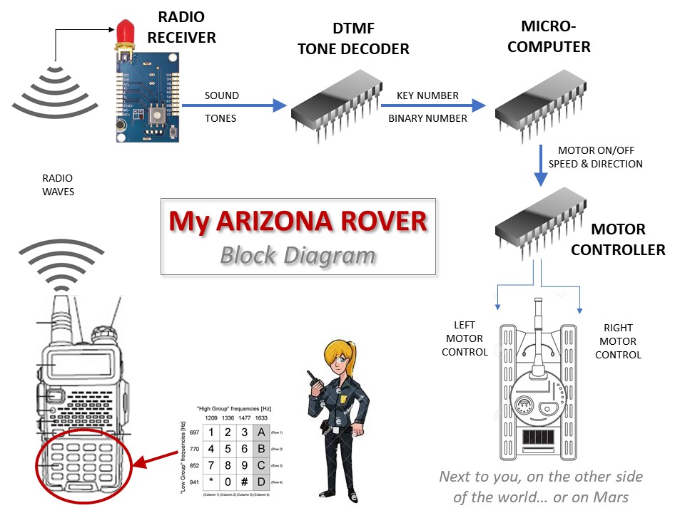
The basic overviiew of how the rover operators is shown at the right. Keys are pressed via a handheld radio, or computer screen, and then those DTMF signals are transmitted to a radio receiver on the rover. The rover converts that signal back to DTMF tones, matching the key pressed and then uses a Micro-computer (MCU) to change the DTMF tone to control signals for both the right and left motors of the rover drive system.
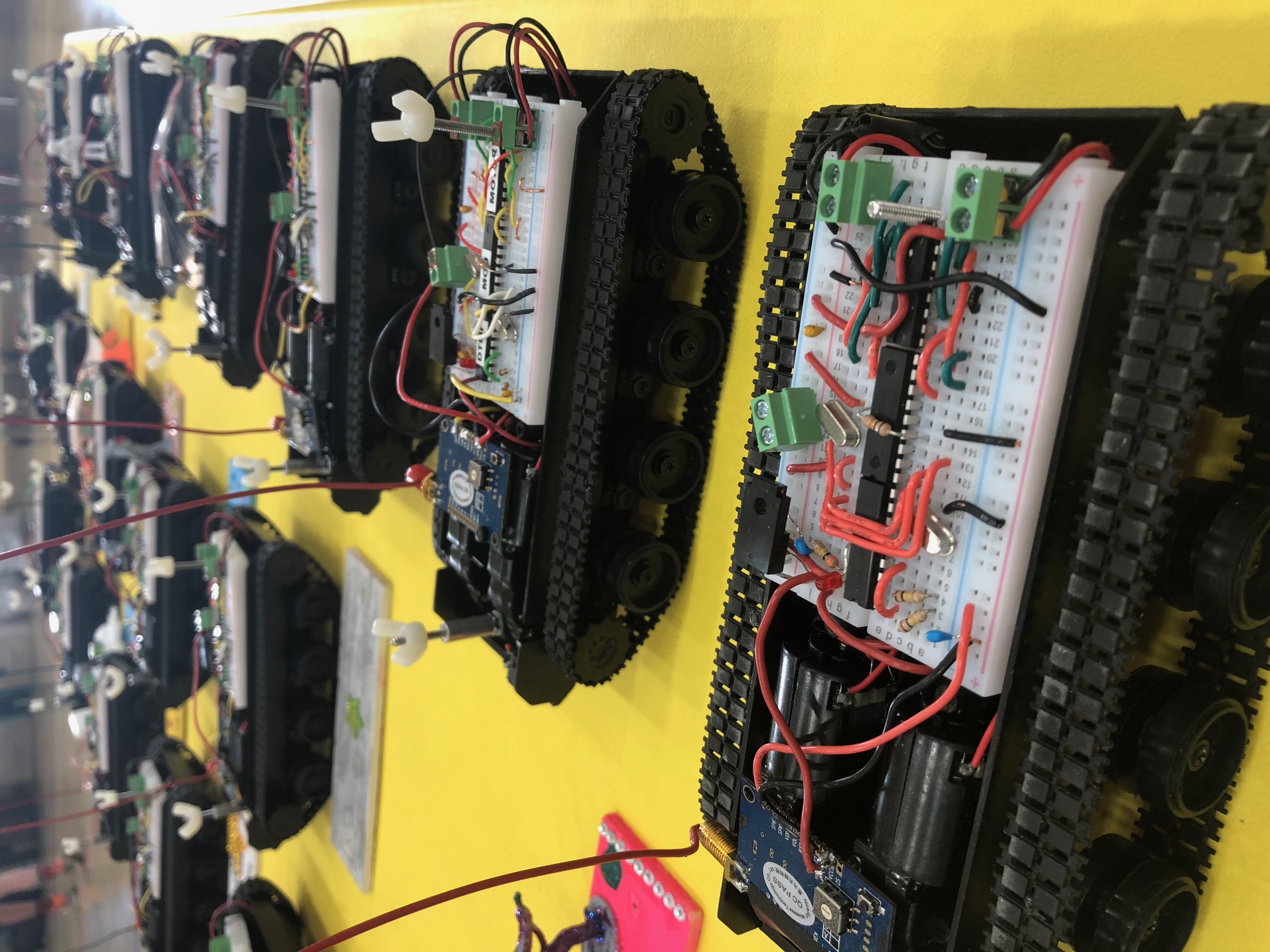
The rover using a simple tank chassis systems driven by tracks and two indepent motors. The motors are powered using Pulse Width Modulation allowing the programming to easily program different speeds and directiions via programming of the MCU.
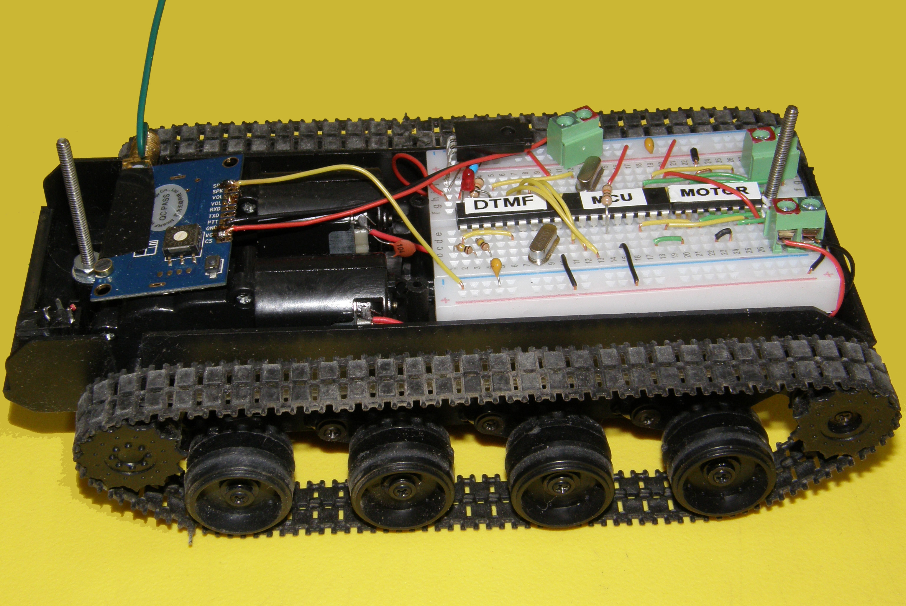 The
rover is shown to the left. From the left, the VHF radio
receiver is mounted onto the tank chassis. Audio signal from the
receiver are fed to a 2-inch by 3-inch breadoard mounted inside the
chasses.
The
rover is shown to the left. From the left, the VHF radio
receiver is mounted onto the tank chassis. Audio signal from the
receiver are fed to a 2-inch by 3-inch breadoard mounted inside the
chasses.
The audio signals first pass through a DTMF decoder to convert the audio signals back to a 4-bit binary representation of the key pressed. Next the binary information is fed into a micro-controller which converts the specific key pressed to motor enable signals and also speed which is managed via pulse width modulation. Finally, this is then fed into each separate motor as three signals.
These signals include an enable/disable motor signal that is pulse width modulated. The remaing two go to separate sides of the motor to control polarity and therefore direction.
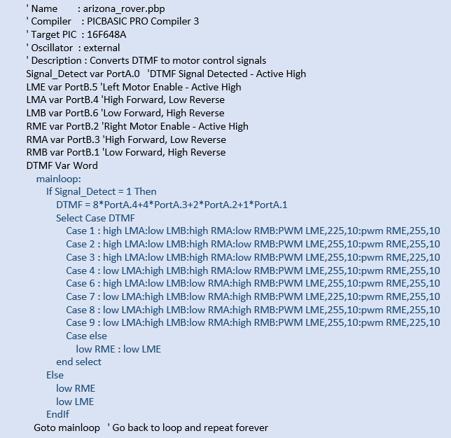
The chasses is power by 4 AA batteries providing six volts which is regulated to 5 volts for the system. Operating time is about 15 minutes. The source code for the MCU is quite simple and shown below:
 The
two long screws on the right and left of the rover allow each student
to mount a lightweight board and decorate it to express their own
individuality which adds quite a bit of creativity and competitive
spirit since the rover design are judged based upon the not just their
ability to complete their missions and function properly, but also for
their artistic creativity and design.
The
two long screws on the right and left of the rover allow each student
to mount a lightweight board and decorate it to express their own
individuality which adds quite a bit of creativity and competitive
spirit since the rover design are judged based upon the not just their
ability to complete their missions and function properly, but also for
their artistic creativity and design.
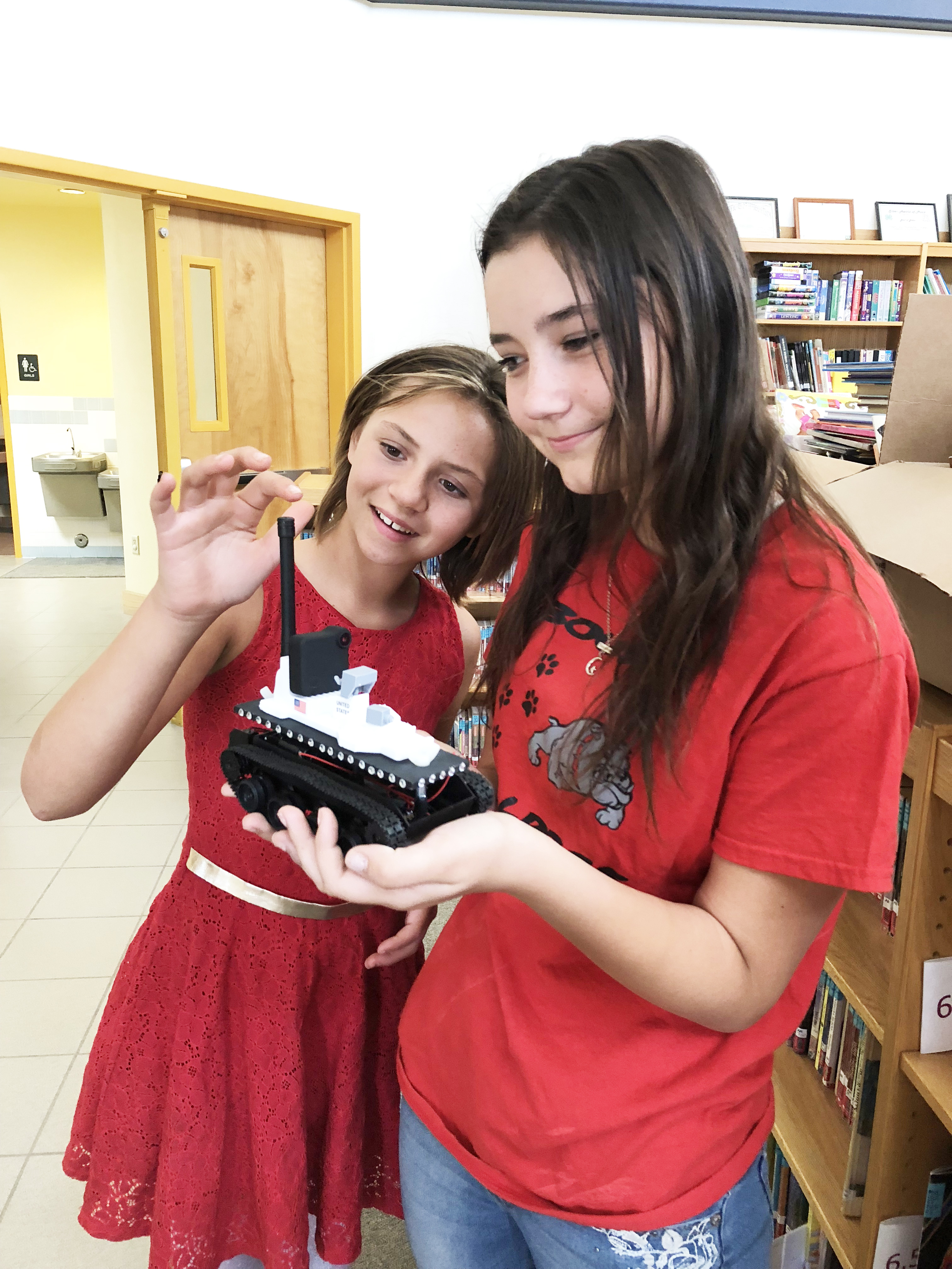
Video signals were transmitted via radio using a RunCam system. Here you can see one of our young leaders, Eliyah, navigating her rover through an underground flourscent cave.
This was our first annual APS Arizona Rover project. It was hosted at Bouse Elementary School in La Paz County Arizone and we want to than APS for help making it possible. We beleive the coming school year may lead to a inter-school rover competition between more schools in La Paz County and from other communities in our region along the Colorado River Valley.
Three youth are already taking the design to the next level with plans to integrate the DTMF decoding into the MCU itself, moving it from a 3-chip to a 2-chip design and reducing component count by about 50%.
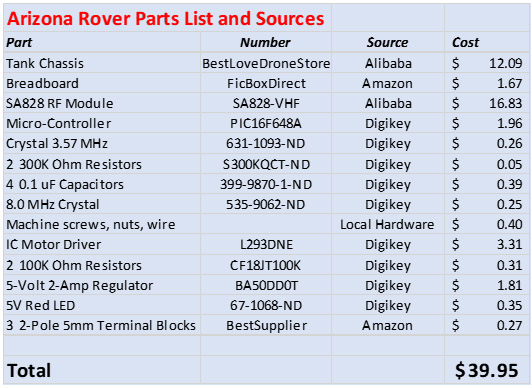
APS Arizona Rover Parts List: :
If you have questions or suggestions, please write to Joe at JEL13722@gmail.com or Dave at K1AN@ARRL.net, mentors for the youth-led Arizona Amateur Radio Association.